


It's easy to assume that designing for 3D printing works in the same way as designing for injection moulding or machining, but additive manufacturing introduces a different set of constraints, many of which don't show up until the part arrives and something isn’t quite right.
A prototype lands on the desk the morning of a client presentation, and the surface is rough, there are support marks on the face the client will hold, and the two halves don't quite fit together.
It happens more often than it should, but more often than not, the issue starts before the build begins, in the design file, process choice, or assumptions around how the part will be manufactured. Below, we look at the most common 3D printing design considerations that catch people out, and what can be done differently.
Getting Wall Thickness Right
A wall that collapses mid-print or snaps during post-processing can set a project back by days. Too thin and the wall won’t print at all, or it comes out fragile. Too thick and it warps during cooling, wastes material, and takes longer than it needs to. It depends on the material, geometry and process, but as a general starting point, many parts require wall thicknesses in the region of 1 to 2mm or more for reliable structural integrity.
Most designers set wall thickness based on how it looks on screen, without considering how it will actually behave during printing. A 0.5mm wall might look perfectly acceptable in CAD, but that doesn’t necessarily mean it will survive the build or post-processing stage. Checking the minimum wall requirements for the specific material and process, before the file is finalised, avoids the most common cause of reprints. It’s one of the areas where 3D printing in design demands a different mindset from traditional manufacturing.
Build Orientation and Surface Finish
A prototype with visible stepping across its top surface, or support marks on the face the client will hold, is rarely a printer problem. It’s almost always an orientation decision made too late. Build orientation affects surface finish, strength, support requirements and the amount of post-processing needed afterwards. For designers whose prototypes are heading into client presentations, it’s one of the most important decisions in the process.
A part printed vertically will often have smoother sides but may be weaker along the layer lines. The same part printed horizontally might be stronger overall, but the top surface can show visible stepping where the layers stack. Overhangs beyond about 45 to 50 degrees from vertical tend to require support structures, which leave marks when removed.
Build orientation isn’t a fixed rule. The best choice depends on which surfaces matter most for the specific application, and there’s almost always a trade-off. In many cases, the optimal orientation also depends on whether the prototype is intended for visual review, functional testing, assembly validation or end-use performance. It’s something we see regularly at Truform, and a quick conversation before printing usually saves a round of reprints. In fact, it’s one of the most overlooked aspects of 3D printing in product design, but one of the easiest to get right.
Overhangs, Supports, and Surface Marks
Support structures leave marks and, for prototypes intended for customer reviews, investor demos or functional evaluations, those marks can significantly affect how the part is perceived. Whenever a design has sections that extend outward with nothing underneath, the part either needs to self-support at a gradual angle or temporary structures must hold it in place during the build.
There are a few ways to reduce the impact:
• Keep overhangs below 45 degrees where possible so the part can self-support
• Add fillets or chamfers to sharp transitions, which print more cleanly than abrupt angles
• Consider splitting the part into sections that print flat and assemble afterwards
• Designing with support removal and finishing in mind from the start produces cleaner results and reduces post-processing time.
The Gap Between Screen and Reality
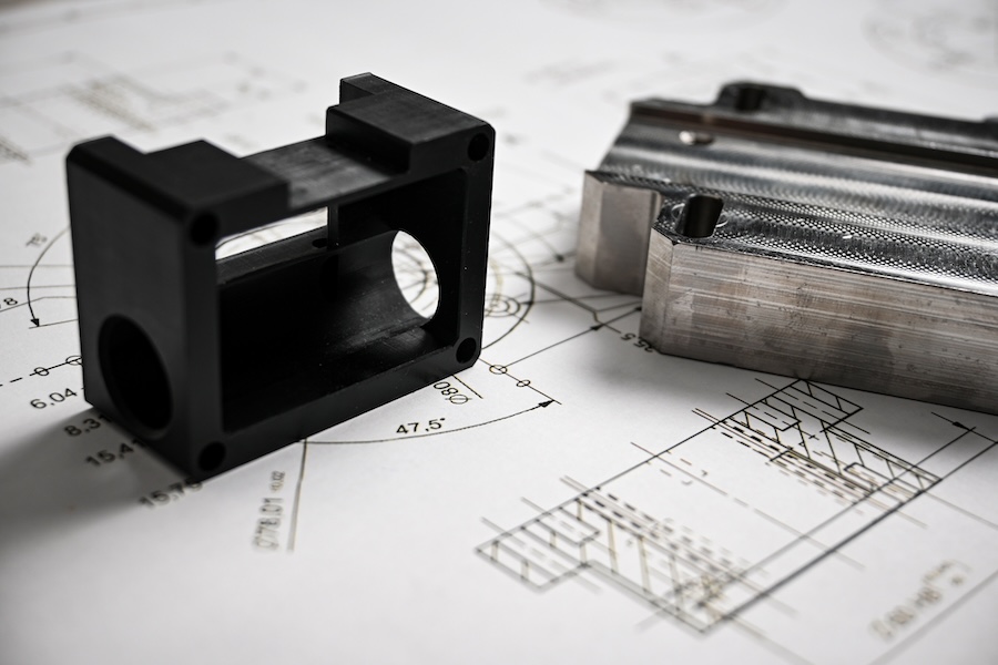
Two halves that fit perfectly in CAD won’t necessarily fit when printed. Every 3D printing process introduces small dimensional variations, as well as factors like material behaviour and build temperature that can shift things just enough to cause problems. Parts that are designed to snap together, slide, or interlock need clearance built into the file to account for these variations. This becomes even more important where printed parts need to interface with machined components, bought-in hardware or legacy assemblies.
In most cases, a clearance of 0.2 to 0.5mm between mating surfaces is enough, though the exact figure depends on the technology. The thing to watch out for is multi-part assemblies, where the parts look right individually, but they don’t fit together, and the whole thing needs redesigning and reprinting. For a designer juggling multiple client projects, that lost round can lead to a missed deadline. Reducing that kind of downtime is as much about design decisions as it is about production speed, something explored further in how on-demand 3D printing reduces downtime in manufacturing.
Why 3D Printing Rewards a Different Design Approach
The most effective use of 3D printing during development in design is as a feedback loop, where each print informs the next version of the file. That shift, where the first print is treated as the starting point rather than the deliverable, is where additive manufacturing starts to unlock its real value.
Many of the mistakes covered here come from applying traditional manufacturing thinking to an additive process. 3D printing in product design allows geometry that traditional methods can’t produce, such as organic shapes, internal channels, and lightweight structures that would be difficult, expensive or impossible to machine or mould. The constraints are different, and understanding them opens possibilities that weren’t there before.
Design for additive manufacturing iteration works best when each round of printing reveals something the screen couldn't: where the walls flex, where the supports leave marks, or where the tolerances are too tight. For designers managing multiple projects with different requirements, having a clear sense of the fundamentals of design for additive manufacturing means fewer surprises along the way.
Avoiding Mistakes Before They Cost Time
Most prototyping delays are avoidable and almost always trace back to design decisions rather than machine failures. Checking wall thickness, considering orientation early, designing for minimal supports, and building in tolerances are all small steps that save significant time later down the line.
Storing validated, print-ready files in a digital inventory helps teams avoid reintroducing old errors into revised designs. Once a file has been optimised for print, it stays optimised.
The teams that get the most from additive manufacturing are the ones that treat the first print as a validation step, not simply the finish line.